Adaptive Optics Retinal Imaging: Applications and Clinical Implications
Dynamic cellular imaging may be the next big clinical advance.
BRIAN KRAWITZ, BA • SHELLEY MO, BA • RICHARD B. ROSEN, MD
Retinal imaging has evolved rapidly over the last 35 years with the development of scanning laser ophthalmoscopy (SLO) and optical coherence tomography. Clinical access to histopathological details for the management of disease has become increasingly valuable, and there are new therapeutic technologies that require cellular level monitoring. The optics of the eye, however, induce wavefront distortions that limit the resolution of conventional imaging instruments to 20 µm, obscuring the finer cellular details of the retina.
Adaptive optics is a novel technology that compensates for the eye’s optical aberrations, enabling unprecedented visualization of many retinal structures in the living eye, including individual photoreceptors, the microvasculature, retinal nerve fiber bundles, the retinal pigment epithelium, and the lamina cribrosa (LC). In this article, we discuss the current abilities and limitations of adaptive optics retinal imaging and its future developments.
Adaptive optics was introduced in astronomical telescopes to compensate for atmospheric turbulence, thereby removing the “twinkling” of starlight to help to resolve celestial objects. The mechanism involves a sensor that detects and measures the wavefront distortions of the light entering the system, transmitting these details to a deformable mirror via a control loop. The deformable mirror inverts the aberrations, correcting the distortions in the wavefront.
Brian Krawitz, BA, and Shelley Mo, BA, are fourth-year medical students at the Icahn School of Medicine of Mount Sinai University in New York, NY. Richard B. Rosen, MD, practices at the New York Eye and Ear Infirmary in New York, NY. Mr. Krawitz and Ms. Mo do not report financial interests in any products mentioned in this article. Dr. Rosen reports financial interests in OD-OS, Carl Zeiss Meditec, and Optovue. Dr. Krawitz can be reached via e-mail at brian.krawitz@icahn.mssm.edu.
Adaptive optics wavefront correction can be applied to a variety of ophthalmic imaging devices to improve their lateral resolution, including fundus cameras and SLOs (Figure 1).
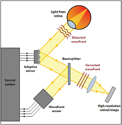
Figure 1. Schematic of adaptive optics retinal imaging system.
PHOTORECEPTORS
Adaptive optics were first applied to the eye to improve the visualization of the cone photoreceptor mosaic. Cones actually act as waveguides, transmitting photons to the light-sensitive molecules in their outer segments.
Junzhong Liang, David Williams, and Donald Miller at the University of Rochester (NY) developed the first adaptive optics fundus camera, which was able to image individual cones at multiple retinal eccentricities.1
This technique was subsequently used to explore how foveal cone arrangement affected color discrimination, applying selective bleaching to isolate the three classes of cone receptors (short [S]-, medium [M]-, and long-[L]-wavelength-sensitive) (Figure 2).2,3
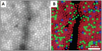
Figure 2. (A) Foveal cone photoreceptor mosaic imaged with an adaptive optics fundus camera and (B) pseudocolor image of the same location with blue, green, and red representing the S, M, and L cones, respectively. Shadows are from overlying blood vessel.2
COURTESY OF NATURE PUBLISHING COMPANY
The development of the first adaptive optics scanning laser ophthalmoscope (AOSLO) greatly enhanced image quality through the use of a confocal pinhole to eliminate out-of-focus light.4 Because reflectance is an indication of cellular integrity, dark gaps produced by non-wave-guiding cones within the photoreceptor mosaic can be used to identify cellular damage. Such abnormalities are commonly discernible in pathological conditions, such as cone rod dystrophies (Figure 3).
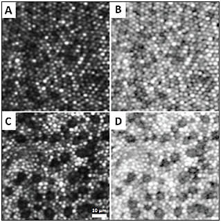
Figure 3. (A and B) Confocal AOSLO images of foveal cones in a healthy subject and (C and D) a patient with cone rod dystrophy. Dark gaps indicate nonwaveguiding cones. Images are displayed in linear scale (left column) and logarithmic scale (right column).
The ability to count cones reliably based on reflectance patterns is attractive for monitoring disease. In a longitudinal study of patients with retinitis pigmentosa, patients receiving ciliary neurotrophic factor exhibited greater preservation of cone density on AOSLO images, compared to the sham-treated group.5 This finding demonstrated the potential application of AOSLO as a sensitive measurement of disease progression and treatment response for clinical trials.
It also may be used to identify candidates with sufficient anatomically preserved but metabolically dysfunctional cones for gene therapy. Scoles et al developed a nonconfocal detection scheme termed split-detection, which revealed the cone inner segment with or without the presence of the wave-guiding outer segments (Figure 4).6 Identification of residual cell structure will help identify patients with photoreceptor degenerations who are most likely to benefit from intervention.
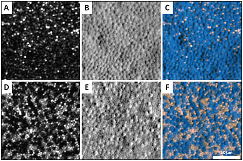
Figure 4. Photoreceptor mosaic at two different retinal eccentricities in a patient with achromatopsia imaged by AOSLO. (A and D) Confocal images; (B and E) Nonconfocal (split-detector) images; and (C and F) color-merged images, where the confocal image is displayed in orange, and nonconfocal image is shown in blue. The inner segments in the nonconfocal images correspond to the dark, nonreflective cones in the confocal images, reflecting intact cone structure that cannot be visualized using confocal AOSLO.6
COURTESY OF THE ASSOCIATION FOR RESEARCH IN VISION AND OPHTHALMOLOGY
For many years, photoreceptor imaging research was limited to cones, until Dubra et al improved the optics of the AOSLO to 2-µm lateral resolution. This level of resolution is sufficient to resolve individual rods, which have more limited wave-guiding properties (Figure 5).7 This ability to differentiate rods from cones in vivo was a major advance toward unraveling the complexity of the photoreceptor mosaic, as well as enabling the study of rod disorders.
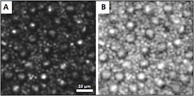
Figure 5. Confocal AOSLO images of the human photoreceptor mosaic, displayed in linear scale (A) and logarithmic scale (B). Smaller cells are rods, and larger cells are cones.7
COURTESY OF OSA PUBLISHING
VASCULATURE
Due to its high magnification, confocality, and resolution, AOSLO can visualize the retinal microvasculature with unprecedented detail, but it is often hampered by lack of contrast. Oral fluorescein administration, coupled with confocal AOSLO (AOSLO FA), enhances the contrast of perfusion maps, enabling the detection of even the finest blood vessels, with image quality far superior to conventional intravenous fluorescein angiography (Figure 6).8
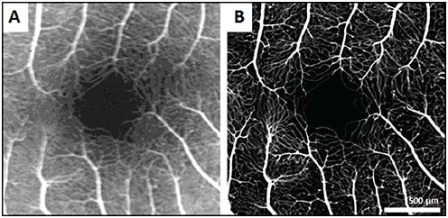
Figure 6. Comparison of IVFA image (A) and AOSLO FA image (B) of fovea in a healthy control.8
COURTESY OF OSA PUBLISHING
Nonconfocal detection schemes can also be used to image the vasculature, employing multiply scattered light in place of exogenous contrast. Chui and Burns pioneered the use of an offset pinhole, a nonconfocal method that utilizes motion contrast processing to create perfusion maps comparable to AOSLO FA, but with the added ability of distinguishing separate capillary plexuses at different depths.
This nonconfocal scheme also reveals delicate vessel wall components not easily seen using confocal AOSLO optics (Figure 7).9,10 Additionally, real-time videos of the vessels can reveal intravascular flow patterns of individual blood cells and enable the measurement of blood flow velocity.
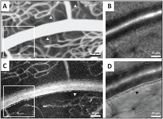
Figure 7. Comparison of AOSLO FA and nonconfocal AOSLO (offset pinhole) at the same location. Nonconfocal perfusion map at this focus shows only superficial capillaries (C) whereas the AOSLO FA perfusion map shows all capillary layers simultaneously (A). Differences in capillary visibility are demarcated with white arrows. Magnified regions indicated by the white boxes in A and C are displayed in B and D. Nonconfocal structural image (D) displays fine vessel wall detail, demarcated with a black arrow, that is not visible on the confocal AOSLO image (B).10
COURTESY OF OSA PUBLISHING
These high-resolution images provide a framework for quantitative and qualitative analysis of the retinal capillaries in microangiopathies. Valuable information that can be extracted includes foveal avascular zone geometry, vessel diameter and wall thickness, vessel density, and microaneurysm morphology (Figure 8). Using this information, we can characterize disease on a microscopic scale.

Figure 8. Confocal AOSLO image (A) and AOSLO FA image (B) of a microaneurysm in a patient with hypertension. Superimposing these images ([C], with [B] in red) shows the relationship between the perfused and nonperfused region.11
COURTESY OF THE ASSOCIATION FOR RESEARCH IN VISION AND OPHTHALMOLOGY
We can also detect subclinical changes that may guide earlier interventions to prevent vision loss. Tam et al showed greater arteriovenous tortuosity surrounding the fovea in type 2 diabetics without retinopathy compared to controls,12 and Burns et al identified subclinical perifoveal microvascular remodeling in patients with nonproliferative diabetic retinopathy.13
Pinhas et al demonstrated a decrease in vessel density in fellow eyes of patients with nonischemic central retinal vein occlusions (Figure 9).14 These findings may serve as biomarkers for the identification of microvascular disease before the onset of clinical deterioration.
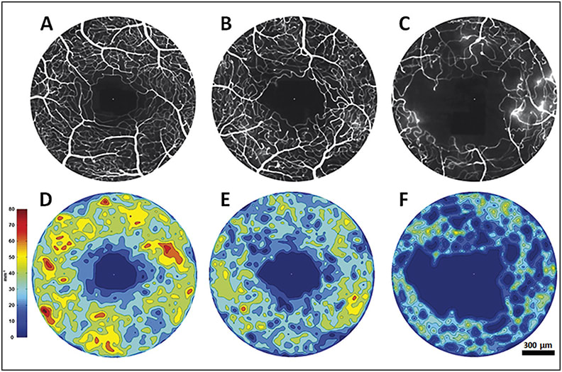
Figure 9. AOSLO FA foveal perfusion maps (top row) and corresponding colorized density contour maps (bottom row) of healthy control eye (A&D), CRVO fellow eye (B&E) and CRVO affected eye (C&F). While the perfusion density is expectantly low in the affected eye, the CRVO fellow eye also exhibits diminished perfusion density compared to the control.14
COURTESY OF WOLTERS KLUWER
Additionally, the ability to apply these imaging techniques longitudinally can provide new insights into the dynamics of vasculopathic progression and resolution. AOSLO images can reveal vascular occlusion and reperfusion of individual capillaries, along with several other manifestations of microvascular remodeling (Figure 10).
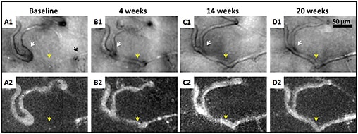
Figure 10. Nonconfocal AOSLO (offset pinhole) structural images (A1-D1) and perfusion maps (A2-D2) of a patient with proliferative diabetic retinopathy. Black arrow indicates a capillary segment with an abrupt end (A1). White arrows indicate that as the neighboring capillary is recanalized and reperfused (yellow arrows), vessel caliber and distortion decrease.15
COURTESY OF JOHN WILEY & SONS, INC.
RETINAL NERVE FIBER BUNDLES
More recently, AOSLO has been utilized to image the retinal nerve fiber layer (RNFL) with delineation of individual nerve fiber bundles.16-19 Hood et al demonstrated the microanatomy of RNFL bundle loss in eyes with glaucoma,20 which may precede RNFL thinning on OCT and visual field defects (Figure 11).
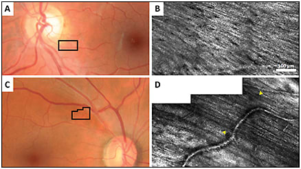
Figure 11. Fundus photographs of a healthy control (A) and a glaucoma patient (C), with black boxes indicating the RNFL area imaged with confocal AOSLO in (B) and (D). (B) reflects a healthy RNFL, whereas the hypofluorescent region demarcated by yellow arrows in (D) reflects an RNFL defect.
RETINAL PIGMENT EPITHELIUM
The RPE plays a crucial role in many ocular diseases. However, photoreceptors mask the signal from the underlying RPE layer, making it difficult to visualize the RPE mosaic with confocal AOSLO.
The application of fundus autofluorescence to AOSLO21 allows for clear visualization of RPE cells, even in patients with intact overlying photoreceptors. This may prove useful to detect initial damage in age-related macular degeneration because the RPE may undergo the earliest changes (Figure 12).
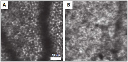
Figure 12. Confocal AOSLO with fundus autofluorescence of healthy patient (A) and patient with AMD (B), where the regularity of the RPE is disrupted. Shadows are from overlying blood vessels.22
COURTESY OF OSA PUBLISHING
LAMINA CRIBROSA
The LC is a porous network of collagenous tissue through which retinal vessels and nerve fibers enter and exit the eye. It has also been imaged using adaptive optics. It is hypothesized that mechanical changes to the LC secondary to pressure abnormalities contribute to early optic nerve damage in glaucoma,23 making this structure a desirable imaging target.
Using confocal AOSLO, we can successfully resolve the LC structure and identify the malformations, such as enlargement of the laminar pore area, that have been found in glaucomatous eyes.24-27
ADDITIONAL STRUCTURES
Using special extrinsic fluorophores, researchers have been able to visualize ganglion cells in living rats, mice, and monkeys.28-31 However, these fluorophores are currently not available for clinical use; hence, the search for ganglion cells in human retinas continues.
Henle fibers were reported in a patient with Best disease,32 although these fibers are not typically visible in normal conditions, except when using directional OCT.33 Finally, choroidal vascular details have been seen only to a limited extent through areas of geographic atrophy.
The weak signal arising from these deep layers has challenged the visualization of subretinal structures in most circumstances, and they remain elusive targets to those seeking the application of adaptive optics to age-related macular degeneration.34
LIMITATIONS
While adaptive optics currently offers the best in vivo look at the microstructure of the retina, there are several limitations to its widespread clinical implementation. Imaging sessions are prolonged and demand excellent subject fixation, as the field of view studied is between 1° and 4°. The system is very sensitive to media opacities, higher refractive error, and tear film deficiencies. Additionally, image processing and analysis are time-consuming processes that lack automated techniques.
Because the majority of the devices are custom-built, access to these imaging systems remains limited. However, with further advancements in the optics and software and as more commercial systems become available, adaptive optics promises to deliver a new level of histopathologic insight as a clinical tool.
CONCLUSION
Adaptive optics is an emerging technology that has revolutionized our ability to study the dynamics of the living retina on the cellular scale. Its clinical applications are just beginning to be realized.
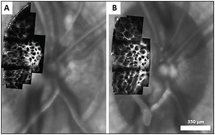
Figure 13. Confocal AOSLO images of lamina cribrosa overlaid on corresponding SLO images in healthy rhesus monkey at baseline (A) and following induction of experimental glaucoma (B). Changes in LC pore geometry are visible between the two imaging sessions.27
COURTESY OF PUBLIC LIBRARY OF SCIENCE
In the near future, adaptive optics imaging promises to help elucidate structure-function relationships, reveal the evolution of pathologies over time, and provide better insight into appropriate management to preserve and improve retinal health. RP
REFERENCES
1. Liang J, Williams DR, Miller DT. Supernormal vision and high-resolution retinal imaging through adaptive optics. J Opt Soc Am A Opt Image Sci Vis. 1997;14:2884-2892.
2. Roorda A, Williams DR. The arrangement of the three cone classes in the living human eye. Nature. 1999;397:520-522.
3. Hofer H, Carroll J, Neitz J, Neitz M, Williams DR. Organization of the human trichromatic cone mosaic. J Neurosci. 2005;25:9669-9679.
4. Roorda A, Romero-Borja F, Donnelly WJ, Queener H, Hebert TJ, Campbell MCW. Adaptive optics scanning laser ophthalmoscopy. Opt. Express. 2002;10:405-412.
5. Talcott KE, Ratnam K, Sundquist SM, et al. Longitudinal study of cone photoreceptors during retinal degeneration and in response to ciliary neurotrophic factor treatment. Invest Ophthalmol Vis Sci. 2011;52:2219-2226.
6. Scoles D, Sulai YN, Langlo CS, et al. In vivo imaging of human cone photoreceptor inner segments. Invest Ophthalmol Vis Sci. 2014;55:4244-4251.
7. Dubra A, Sulai Y, Norris JL, et al. Noninvasive imaging of the human rod photoreceptor mosaic using a confocal adaptive optics scanning ophthalmoscope. Biomed Opt Express. 2011;2:1864-1876.
8. Pinhas A, Dubow M, Shah N, et al. In vivo imaging of human retinal microvasculature using adaptive optics scanning light ophthalmoscope fluorescein angiography. Biomed Opt Express. 2013;4:1305-1317.
9. Chui TY, Vannasdale DA, Burns SA. The use of forward scatter to improve retinal vascular imaging with an adaptive optics scanning laser ophthalmoscope. Biomed Opt Express. 2012;3:2537-2549.
10. Chui TY, Dubow M, Pinhas A, et al. Comparison of adaptive optics scanning light ophthalmoscopic fluorescein angiography and offset pinhole imaging. Biomed Opt Express. 2014;5:1173-1189.
11. Dubow M, Pinhas A, Shah N, et al. Classification of human retinal microaneurysms using adaptive optics scanning light ophthalmoscope fluorescein angiography. Invest Ophthalmol Vis Sci. 2014;55:1299-1309.
12. Tam J, Dhamdhere KP, Tiruveedhula P, et al. Disruption of the retinal parafoveal capillary network in type 2 diabetes before the onset of diabetic retinopathy. Invest Ophthalmol Vis Sci. 2011;52:9257-9266.
13. Burns SA, Elsner AE, Chui TY, et al. In vivo adaptive optics microvascular imaging in diabetic patients without clinically severe diabetic retinopathy. Biomed Opt Express. 2014;5:961-974.
14. Pinhas A, Dubow M, Shah N, et al. Fellow eye changes in patients with nonischemic central retinal vein occlusion: assessment of perfused foveal microvascular density and identification of nonperfused capillaries. Retina. 2015;35:2028-2036.
15. Chui TY, Pinhas A, Gan A, et al. Longitudinal imaging of microvascular remodelling in proliferative diabetic retinopathy using adaptive optics scanning light ophthalmoscopy. Ophthalmic Physiol Opt. 2016 Jan 24. [Epub ahead of print]
16. Chen MF, Chui TY, Alhadeff P, et al. Adaptive optics imaging of healthy and abnormal regions of retinal nerve fiber bundles of patients with glaucoma. Invest Ophthalmol Vis Sci. 2015;56:674-681.
17. Huang G, Gast TJ, Burns SA. In vivo adaptive optics imaging of the temporal raphe and its relationship to the optic disc and fovea in the human retina. Invest Ophthalmol Vis Sci. 2014;55:5952-5961.
18. Takayama K, Ooto S, Hangai M, et al. High-resolution imaging of the retinal nerve fiber layer in normal eyes using adaptive optics scanning laser ophthalmoscopy. PLoS One. 2012;7:e33158.
19. Ramaswamy G, Lombardo M, Devaney N. Registration of adaptive optics corrected retinal nerve fiber layer (RNFL) images. Biomed Opt Express. 2014;5:1941-1951.
20. Hood DC, Chen MF, Lee D, et al. Confocalaadaptive optics imaging of peripapillary nerve fiber bundles: implications for glaucomatous damage seen on circumpapillary OCT scans. Transl Vis Sci Technol. 2015;4:12.
21. Morgan JI, Dubra A, Wolfe R, Merigan WH, Williams DR. In vivo autofluorescence imaging of the human and macaque retinal pigment epithelial cell mosaic. Invest Ophthalmol Vis Sci. 2009;50:1350-1359.
22. Rossi EA, Rangel-Fonseca P, Parkins K, et al. In vivo imaging of retinal pigment epithelium cells in age related macular degeneration. Biomed Opt Express. 2013;4:2527-2539.
23. Varma R, Quigley HA, Pease ME. Changes in optic disk characteristics and number of nerve fibers in experimental glaucoma. Am J Ophthalmol. 1992;114:554-559.
24. Sredar N, Ivers KM, Queener HM, Zouridakis G, Porter J. 3D modeling to characterize lamina cribrosa surface and pore geometries using in vivo images from normal and glaucomatous eyes. Biomed Opt Express. 2013;4:1153-1165.
25. Vilupuru AS, Rangaswamy NV, Frishman LJ, Smith EL 3rd, Harwerth RS, Roorda A. Adaptive optics scanning laser ophthalmoscopy for in vivo imaging of lamina cribrosa. J Opt Soc Am A Opt Image Sci Vis. 2007;24:1417-1425.
26. Akagi T, Hangai M, Takayama K, Nonaka A, Ooto S, Yoshimura N. In vivo imaging of lamina cribrosa pores by adaptive optics scanning laser ophthalmoscopy. Invest Ophthalmol Vis Sci. 2012;53:4111-4119.
27. Ivers KM, Sredar N, Patel NB, et al. In vivo changes in lamina cribrosa microarchitecture and optic nerve head structure in early experimental glaucoma. PLoS One. 2015;10:e0134223.
28. Yin L, Geng Y, Osakada F, et al. Imaging light responses of retinal ganglion cells in the living mouse eye. J Neurophysiol. 2013;109:2415-2421.
29. Yin L, Masella B, Dalkara D, et al. Imaging light responses of foveal ganglion cells in the living macaque eye. J Neurosci. 2014;34:6596-6605.
30. Geng Y, Greenberg KP, Wolfe R, et al. In vivo imaging of microscopic structures in the rat retina. Invest Ophthalmol Vis Sci. 2009;50:5872-5879.
31. Geng Y, Dubra A, Yin L, et al. Adaptive optics retinal imaging in the living mouse eye. Biomed Opt Express. 2012;3:715-734.
32. Scoles D, Higgins BP, Cooper RF, et al. Microscopic inner retinal hyper-reflective phenotypes in retinal and neurologic disease. Invest Ophthalmol Vis Sci. 2014;55:4015-4029.
33. Lujan BJ, Roorda A, Croskrey JA, et al. Directional optical coherence tomography provides accurate outer nuclear layer and Henle fiber layer measurements. Retina. 2015;35:1511-1520.
34. Roorda A, Duncan JL. Adaptive optics ophthalmoscopy. Annu Rev Vis Sci. 2015;1:19-50.


